
Table of Contents
Project Overview
The Situation
Many EV charging projects begin with ambitious targets, only to be constrained by the utility interconnection. In this case, the developer had access to 200 kW at the point of common coupling (PCC). This was the maximum import capacity supported by the existing infrastructure and was paired with a strict zero-export requirement. No additional service capacity was available, and utility upgrades were not feasible.
Despite these limits, the economic value of deploying high-power DC fast chargers justified moving forward. The challenge became designing an architecture capable of supporting more than 1.4 MW of charging capacity while never exceeding 200 kW of grid import.
Solution Summary
-
System Type: Hybrid Energy Architecture with Battery Energy Storage
-
Grid Connection: 200 kW maximum import with zero-export requirement
-
Charging Capacity: 6 DC fast chargers, up to 240 kW each (1.4+ MW total)
-
Configuration: Multi-MWh AES Cabinet battery storage with integrated solar generation
-
Key Benefits: Megawatt-scale charging on constrained grid, solar self-consumption, predictable interconnection
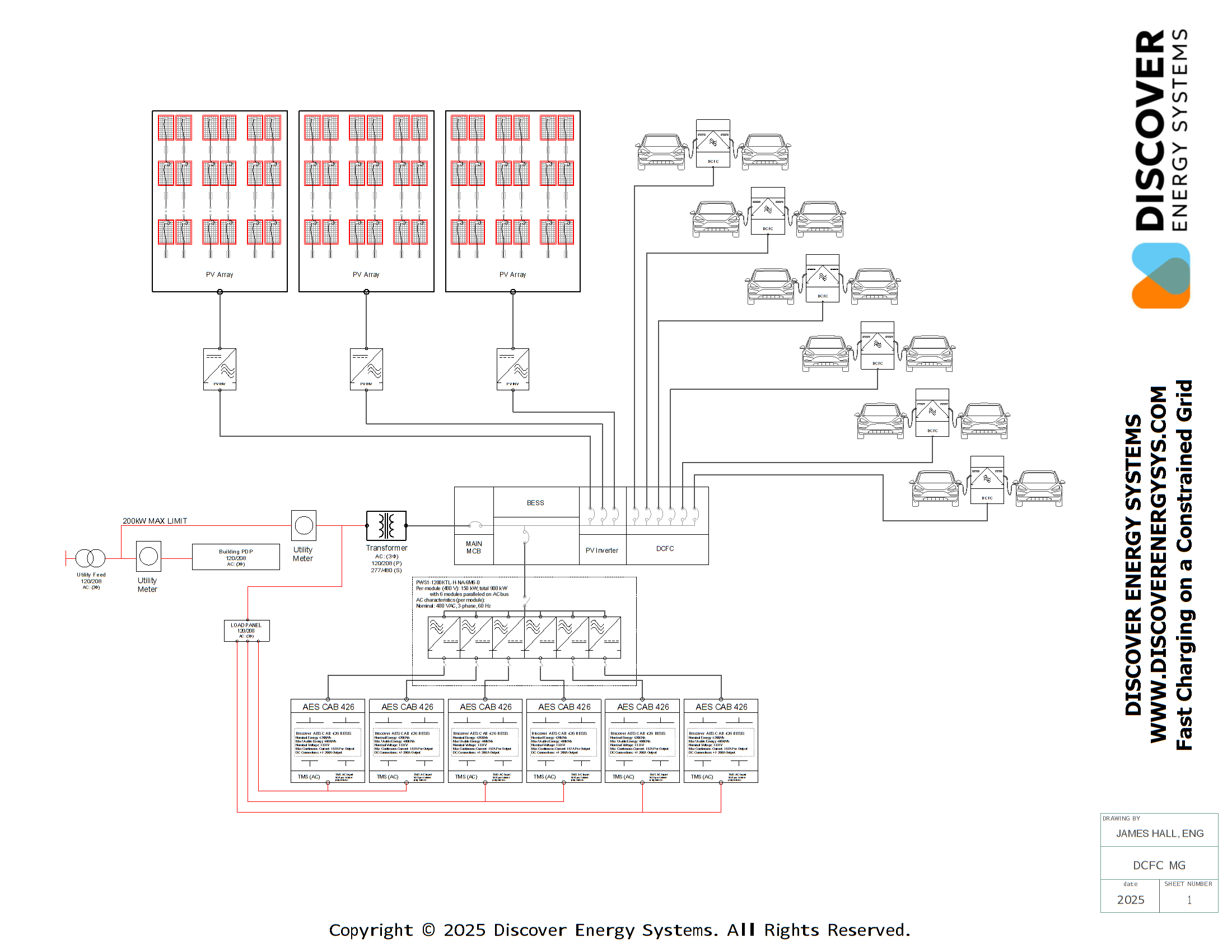
System Diagram (Single-Line Drawing)

The Challenge
Project Requirements
The developer planned to deploy six high-power DC fast chargers, each up to 240 kW. With a combined potential load exceeding 1.4 MW, the math did not work with a traditional grid-connected design. The site needed to:
- Operate within a strict 200 kW import limit
- Maintain zero export at all times
- Support large, fast load swings from EV chargers
- Integrate on-site solar without violating interconnection rules
Industry Context
This combination of requirements is becoming common across commercial and fleet charging projects. Many ideal charging locations have constrained grid service, where large upgrades are expensive, slow, or unavailable altogether.
The Hybrid Energy Architecture
Overview
The solution was to build a hybrid on-site power plant centered around multi-MWh battery energy storage using the AES Cabinet Solutions. These high-voltage outdoor cabinets supply the instantaneous power and energy capacity needed to respond to EV charging demand that far exceeds grid availability.
Energy Storage System
- Battery Platform: AES Cabinet Solutions for multi-MWh capacity
- Power Output: High-voltage outdoor cabinets for instantaneous power delivery
- Response Time: Immediate response to fast load swings from DC fast chargers
- Design Purpose: Bridge gap between available grid capacity and charging demand
Learn about Discover Energy Systems' AES CAB product
Solar Integration
On-site solar generation is fully integrated into the system, but under a strict rule enforced by the Energy Management System (EMS):
All PV output must be consumed on site or curtailed, guaranteeing zero export.
- Primary Use: Offset EV charging demand in real-time
- Secondary Use: Charge battery when headroom is available
- Grid Protection: Never allowed to push power back onto utility grid
- Curtailment Logic: EMS curtails PV when site cannot absorb all generation
System Integration
- Common Bus: All energy sources and loads operate on 480 VAC distribution bus
- Real-Time Coordination: EMS coordinates dispatch across all assets
- Load Management: Dynamic power allocation to DC fast chargers
- Compliance Enforcement: Continuous monitoring of import and export limits
How the System Operates
Operating Boundaries
The EMS governs the site by enforcing three strict operating boundaries:
- Grid import must never exceed 200 kW
- DCFC load must remain within the site's available power resources
- PV generation must never export to the grid under any condition
High-Demand Operation
- Battery Discharge: Supplies additional power to maintain grid import compliance
- DCFC Allocation: Power distributed to chargers within available resources
- Grid Limit Protection: Never exceeds 200 kW import regardless of charging demand
- Load Balancing: Real-time allocation across multiple charging sessions
Low-Demand Operation
- Battery Recharging: Solar generation and grid headroom restore battery capacity
- Solar Utilization: PV output charges battery or directly powers chargers
- Grid Optimization: Uses available import capacity when charging demand is low
- Zero Export Compliance: Excess PV curtailed to prevent grid export
Constrained Resource Management
If available resources become constrained, such as when the battery approaches discharge limits or PV output is low, the EMS dynamically throttles DCFC power to match the sustainable capacity of the site. This prevents overload events and ensures the system always operates within safe and compliant boundaries.
Control Strategy
- Real-Time Monitoring: Continuous tracking of all energy sources and loads
- Predictive Management: Anticipates charging patterns and solar generation
- Dynamic Throttling: Adjusts charger power to match available resources
- Safety Compliance: Maintains stable, predictable site performance
Learn about Discover Energy Systems' C&I controls
This coordinated control strategy enables megawatt-scale fast charging on a 200 kW grid connection while maintaining stable and predictable site performance.
Why Developers Use This Model
Overcoming Grid Constraints
This architecture gives developers a way to deploy high-power EV charging without depending on utility expansion. Many ideal charging locations have constrained grid service, making this solution particularly valuable.
Key Advantages
- Megawatt-class charging with constrained infrastructure - Deploy high-power charging without waiting for utility upgrades
- Solar self-consumption for lower operating costs - Reduce energy costs through on-site generation
- Fast dynamic power support from DES BESS Solutions - Instantaneous response to charging demand
- Predictable interconnection and permitting pathway - Simplified approval process with zero-export compliance
- Scalable from hundreds of kilowatt-hours to multi-MWh installations - Grow capacity as demand increases
Project Risk Reduction
For developers and site owners, this model reduces project risk and accelerates deployment timelines by:
- Eliminating dependency on utility service upgrades
- Providing clear regulatory compliance pathway
- Enabling deployment in high-value locations with grid constraints
- Delivering immediate revenue generation without infrastructure delays
A Replicable Blueprint
The Fundamental Shift
This use case shows that high-power EV charging no longer depends on high-power grid service. With energy storage as the backbone, solar as a cost reducer, and an EMS enforcing both import limits and zero export, developers can deliver the charging capacity they need using the grid capacity they have.
The Architecture in Brief
A simple single-line diagram makes the concept immediately clear:
Solar and grid feed the site, storage fills the power gap, and the grid remains stable and capped.
Universal Application
This is a scalable, repeatable blueprint for any grid-constrained EV charging project, including:
- Commercial DC fast charging stations
- Fleet charging depots
- Highway corridor charging
- Urban charging hubs
- Workplace charging installations
- Multi-family residential charging
Next Steps
Developers and site owners interested in deploying this architecture can leverage proven, standardized components and design patterns to accelerate their projects and deliver megawatt-scale charging in grid-constrained environments.
Contact us to discuss your grid-constrained EV charging project

Table of Contents
Project Overview
The Challenge
Why this project came to be.
-
High operational energy costs from peak demand charges
-
Need for reliable backup power for critical operations
-
Desire for energy independence and sustainability goals
-
Complex facility power requirements (elevators, HVAC, lighting, equipment)
Solution Summary
-
System Type: AC-Coupled Microgrid Architecture
-
Total Capacity: 1MW solar generation + 3.34MWh energy storage
-
Configuration: Eight AES CAB 426 battery cabinets with six 100kW solar inverters
-
Applications: Peak shaving, backup power, energy independence, grid services
-
Key Benefits: 99.9% power reliability, significant cost savings, environmental impact reduction
System Diagram (Single-Line Drawing)

AC Couple PV Distribution
Overview
The system accommodates up to 1MW of AC-coupled photovoltaic (PV) input, forming the primary energy generation source within the microgrid. The configuration includes six Solis S5 100kW three-phase string inverters, each operating at 480VAC with nominal 120A output per unit.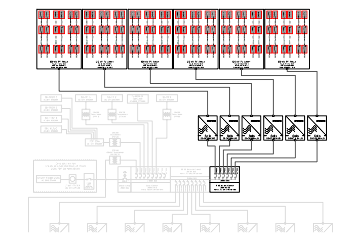
Inverter Specification
- Model: Solis S5 100kW three-phase string inverters
- AC Output: 480VAC, 3-phase, 120A nominal per unit
- DC Input: Ten independent MPPT inputs per inverter
- MPPT Voltage Range: 180-1000V with up to 1000VDC and 50A Isc per channel
- PV String Flexibility: Designed for high granularity and precise optimization
Electrical Integration
- AC Bus Configuration: All six inverters paralleled on dedicated AC bus
- Safety Compliance: Each unit connected to PV breaker cabinet via dedicated breaker
- Breaker Cabinet Functions: Houses individual disconnects for each inverter
- Motor-Based Control: Supports both manual lockout/tagout and automated control
Controls and Communication
- Communication Protocol: Modbus TCP/IP with direct interfacing to site MGC
- Active Power Control: Real-time export limiting, PV smoothing, and dynamic derating
- Grid Integration: Seamless operation alongside battery PCS units and utility connection
- Monitoring Capabilities: Real-time balancing and performance optimization
Learn about Discover Energy Systems' C&I controls
Expandability & Design Considerations
- Future Integration: Additional AC-coupled PV inverters can be installed on load side branch circuits
- Capacity Limitations: Expansion must consider feeder capacity, voltage drop/rise tolerances
- System Coordination: Protective coordination with existing system required
- Hybrid Compatibility: Seamless operation alongside battery PCS units and generator input
Energy Storage Subsystem Distribution
Overview
The energy storage system is designed specifically for off-grid or grid-independent operation. The BESS provides the backbone of energy stability for the microgrid, ensuring seamless operation during periods of insufficient PV generation. Grid or co-generation sources are only utilized as backup during sustained PV generation deficits.

Capacity and Architecture
- Total Installed Capacity: 3.34 MWh usable energy (3.41 MWh rated)
- Configuration: Eight AES CAB 426 battery cabinets, each with 418 kWh capacity
- Design Considerations: Fully modular for easy scaling to match site growth
- Redundancy: Multiple levels ensuring any single cabinet can be taken offline without disabling the system
- Maintenance: Allows selective maintenance or service with no interruption to site power
Learn about Discover Energy Systems' AES CAB product
Power Conversion System (PCS)
- Inverter Pairing: Each battery cabinet directly paired with Sinexcel PWS1-160M-H-NA battery inverter
- Power Rating: 160 kW AC derated output, 125 kW continuous across all eight PCS units
- Electrical Protection: Each PCS protected and isolated via individual breaker within BESS breaker cabinet
- System Synchronization: All PCS units synchronized and paralleled on common AC bus
Electrical Integration
- Bus Configuration: Multi-branch modularity to facilitate segmented operation
- Service Isolation: Thermal coordination and operational reliability through centralized switchgear
- Distribution Integration: Centralized point for interconnection to switchgear or distribution nodes
Communication and Control
- EMS Integration: Micro-Grid Control System (MGC) interfaces with all PCS units via Modbus TCP/IP
- Real-Time Dispatch: Logic implemented for battery charge/discharge control
- Load Response: Dynamic response to load profiles and PV production variability
- Safety Management: Operational safety limits, temperature monitoring, and fault conditions
- Autonomous Operation: PCS adheres to MGC commands autonomously
Learn about Discover Energy Systems' C&I controls
Operational Role
- Primary Function: Main buffer and dispatchable energy reserve within the microgrid
- Load Support: Smooths out fluctuations in PV generation and supports loads during night/low-irradiance periods
- Grid Independence: Maintains system operation when both PV and external grid are unavailable
- Backup Integration: Coordinated through MGC when both PV and storage are unable to meet critical load demands
MGC, Load Distribution, and Interconnect Subsystem
Overview
The Microgrid Control (MGC), load distribution, and interconnect subsystem manages power flow, load prioritization, and grid interface for the entire facility. This subsystem ensures reliable power delivery to critical loads while maintaining safe operation and grid compliance.
Learn about Discover Energy Systems' microgrid controls
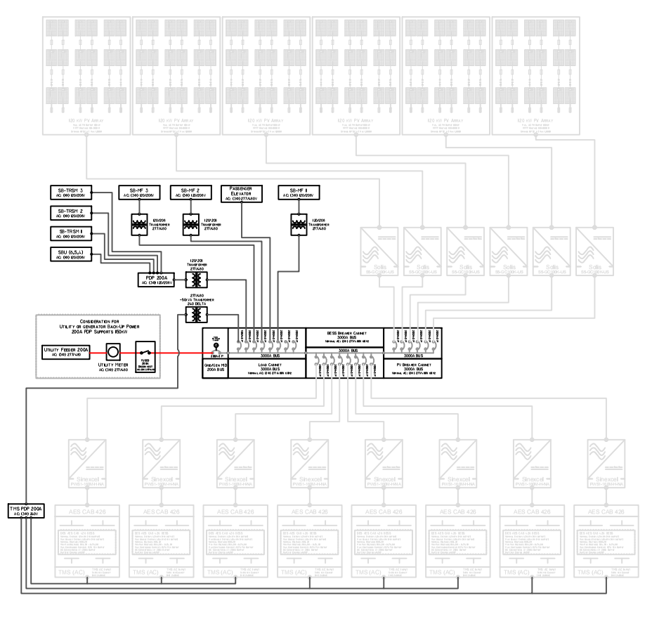
Load Cabinet
Configuration and Expandability
- Initial Buildout: Six dedicated branch circuits with individual protection
- Scalability: Supports up to twelve individually protected load circuits
- Breaker Ratings: Each branch circuit can accommodate breakers rated up to 250A
- Load Profiles: Suitable for range of commercial and industrial load profiles
- Power Distribution: Delivers conditioned power from shared AC bus (fed by PV and BESS)
Functional Role
- Primary Distribution Point: Delivers conditioned power from shared AC bus to site loads
- DER Accommodation: Allows for connection of additional distributed energy resources
- Load Management: Fully compatible with site-level load shedding strategies
- Circuit Control: MGC can open non-critical load circuits during undergeneration, islanding events, or grid recovery transitions
- Maintenance Support: Selective circuit isolation for maintenance or fault events without full system interruption
Grid/Generator Interface (Microgrid Interconnect Device | MID)
Interface and Breaker Design
- Breaker Rating: Motor-actuated 200A breaker for utility interconnection
- External Sources: Interfaces microgrid with external AC sources (utility grid and/or generators)
- Design Intent: Used for supplemental power only when internal generation (PV + BESS) cannot meet load demand
- Grid Integration: Supports import operation with utility up to ~160kW
- Generator Support: Supports parallel genset operation managed via CANbus under MGC control
Supported Operational Modes
- Grid-Connected Mode: Allows import operation with utility up to ~160kW
- Grid-Independent Mode: Engaging only when PV and BESS are depleted or insufficient
- Generator Support Mode: Supports parallel operation with one or more generators integrated via CANbus
- Staged Genset Operation: Enables staged genset ramp-up, synchronization, and safe breaker closure
- Co-Generation: Multiple generation assets can operate simultaneously with proper synchronization
- Economic Dispatch: Flexible dispatching of generation assets based on demand, availability, and cost optimization
Protection and Sequencing
- Logic Control: Breaker sequencing and interlock conditions driven by Microgrid Controller (MGC)
- Anti-Backfeed: Prevents unintentional export during grid outages or maintenance
- Grid Synchronization: Monitors phase, voltage, and frequency to ensure safe parallel operation
- Transfer Commands: Provides open/close commands to prevent overlapping supply conditions
- Fault Protection: Upon detecting grid loss or instability, MGC isolates MID and transitions to standalone mode
- Reconnection Safety: Grid parameters validated before MID closure after outage recovery