Solar panels and battery storage deliver lower electricity bills, energy resilience, and long-term independence from rising utility rates. But every homeowner faces one major question: Should you buy your solar + storage system, or lease it from a third party?
On the surface, leasing seems attractive. There is low or no upfront cost, maintenance is included, and you get immediate bill savings. However, buying gives you ownership, access to rebates, and greater lifetime savings. When installing Discover Energy Systems’ HELIOS ESS lithium battery, which has the lowest-cost-per-kWh storage solution in its class, the financial advantage of ownership is more apparent than ever.
The following illustrates the costs and benefits of buying vs. leasing solar + storage.
(This article will look at the leasing option only in third-party ownership systems. We will not examine the other third-party option, the power purchase agreement.)
Buying Solar + Storage with HELIOS ESS
Purchasing your solar + storage system means you own the equipment and all the value it produces. Rebates, tax credits, and bill savings flow directly to you—not a leasing company. With Discover’s HELIOS ESS, buyers get a scalable, high-performance battery at the best price per kWh on the market, maximizing both incentives and ROI.
Typical Costs (10 kW solar + 32 kWh HELIOS ESS battery)
|
Item |
Cost (USD) |
|---|---|
|
Solar panels (10 kW @ $1/W) |
$10,000 |
|
2 x HELIOS ESS (32 kWh @ $225/kWh) |
$7,200 |
|
Inverter, wiring, and peripheral equipment |
$8,000 |
|
Installation & labor |
$7,000 |
|
Gross system cost |
$32,200 |
|
Federal ITC (30%) expires 12/2025 |
-$15,000 |
|
Local rebates (varies depending on region) |
-$5,000 |
|
Net cost to owner |
$12,200 |
NOTE: If the cost of electricity in your area is $2000 per year, the system pays for itself in about 6 years.
Financing Solar + Storage
Most people do not have the cash to purchase their solar + storage system. They will take out a loan to finance the purchase. Financing will give you all the benefits of buying, but it will add an extra cost to fund the loan.
Typical Costs (10 kW solar + 32 kWh HELIOS ESS battery + Loan)
|
Item |
Cost (USD) |
|---|---|
|
Solar panels (10 kW @ $1/W) |
$10,000 |
|
2 x HELIOS ESS (32 kWh @ $225/kWh) |
$7,200 |
|
Inverter, wiring, and peripheral equipment |
$8,000 |
|
Installation & labor |
$7,000 |
|
Gross system cost |
$32,200 |
|
Federal ITC (30%) expires 12/2025 |
-$15,000 |
|
Local rebates (varies depending on region) |
-$5,000 |
|
Loan Amount |
$12,200 |
|
Financing Cost (8%) |
$2,652 |
|
Monthly Payment (4 years) |
$310 |
|
Net cost to owner |
$14,852 |
NOTE: If the cost of electricity in your area is $2,000 per year, the system pays for itself in about 7.5 years.
Leasing Solar + Storage
Leasing eliminates upfront costs. You pay a fixed monthly fee while the leasing company owns the system, collects incentives, and maintains it. You benefit from bill savings, but without ownership, the leased solar + storage will provide zero, or even negative, resale value.
Typical Lease Terms (same 10 kW + 32 kWh system)
|
Item |
Cost (USD) |
|---|---|
|
Upfront payment |
$0 – $1,000 |
|
Monthly lease payment |
$250 – $300 |
|
Lease term |
20 years |
|
Annual cost ($250 × 12) |
$3,000 |
|
Total lease payments |
$60,000 |
|
Ownership at end of term |
No (option to renew or buy at fair market value) |
NOTE:
- You cannot select the desired equipment in a leased system. The solar leasing company determines the installed equipment.
- When it comes to maintenance, you are dependent on the leasing company. If the system goes down and it takes a week to restore, the homeowner must pay for power from the utility during that time and is not reimbursed for this additional expense.
Pros and Cons
The following table lists the pros and cons between purchasing, financing, and leasing your solar + storage system.
|
Category |
Buying System with HELIOS ESS |
Financing System with HELIOS ESS |
Leasing System (any equipment) |
|
Electric bill savings |
PRO |
PRO |
PRO |
|
Rebates & incentives |
PRO |
PRO |
CON |
|
Financing cost |
PRO |
CON |
CON |
|
Maintenance |
CON |
CON |
PRO |
|
Resale value |
PRO |
PRO |
CON |
|
System ownership |
PRO |
PRO |
CON |
Lifetime Financial Comparison (20 Years)
|
Metric |
Buying System |
Financing System |
Leasing System |
|
S |
$12,200 |
14,852 |
$60,000 |
|
Total bill savings (20 yrs) |
$40,000 (2,000/yr) |
$40,000 (2,000/yr) | $40,000 (2,000/yr) |
|
Rebates & ITC benefit |
$20,000 |
$20,000 |
$0 |
|
Maintenance (20 yrs) |
($6,000) |
($6,000) |
$0 |
|
Net 20-year |
$21,800 |
$19,148 |
($20,000) |
Over a period of 20 years, leasing the system costs much more than the savings you can achieve on your utility bill.
If you buy or finance the system, with rebates and utility bill savings, the system pays for itself within 6 to 8 years and nets you $20,000 in the long run.
HELIOS ESS Makes Buying Even Better
By purchasing your solar + storage system, you have a choice on what equipment to install. You don’t have to accept any system; you can ask to use the HELIOS ESS.
Discover’s HELIOS ESS isn’t just another battery—it’s engineered for value and performance:
- Lowest $/kWh on the market, stretching every rebate dollar.
- Modular, scalable design to grow with your needs.
- Long cycle life and high efficiency for better performance.
- Seamless integration with leading hybrid inverters.
Buying a HELIOS ESS system is the clear choice when you combine these advantages.
Conclusion
Leasing may sound appealing because it reduces upfront costs, but dollar for dollar, it leaves you paying significantly more over time with nothing to show for it. Buying a solar + storage system based around Discover’s HELIOS ESS ensures you get every incentive, maximize long-term savings, and add real value to your property.
If you’re serious about energy independence and financial return, buying a HELIOS ESS solar + storage system is the smarter investment.
For more information on the HELIOS ESS, click here.
Other Blogs
Introduction
British Columbians looking to lower their electricity bills and embrace clean energy have allies in BC Hydro and Discover Energy Systems.
- BC Hydro offers a substantial solar and battery storage rebate for residential customers: $5,000 for solar panels and an additional $5,000 for battery storage.
- Discover Energy Systems, based in Richmond, BC, sells the HELIOS ESS lithium battery, the lowest-priced (per kWh) residential lithium battery on the market, which maximizes the benefit of adding battery storage to a PV solar system.
Read on to learn more about the BC Hydro rebate and Discover lithium batteries.
BC Hydro Solar and Battery Storage Rebate

This rebate program is offered in coordination with BC Hydro's Self-Generation Program (formerly known as Net Metering). The self-generation program allows you to generate electricity, use what you need, and send any excess energy back to the grid for credits on your bill.
Calculating the Rebate
- Solar Panels
$1,000 per kilowatt (kW) of installed solar panels, including installation and peripheral equipment, up to a maximum of $5,000. - Battery Storage
$500 per kilowatt-hour (kWh), including installation and peripheral equipment, up to $5,000. Minimum storage size of 5 kWh.
Calculating the Cost of a Solar + Battery System
Most installers will tell you that the battery storage portion of a solar + storage system is the most expensive part. The HELIOS ESS is changing that narrative.
The HELIOS ESS from Discover Energy Systems is a game-changer in the battery storage industry. Per kilowatt hour (kWh), the HELIOS ESS is priced below all its competitors. The following graph compares the cost per kWh of leading battery brands, based on data readily available on the Internet.
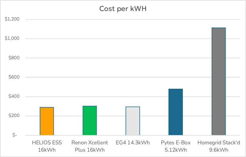
Based on the cost of Discover’s HELIOS ESS batteries, you can purchase MORE storage for harvested PV energy, which you can then use at your convenience.
The HELIOS ESS uses utility-grade battery cells to achieve a better price point and better performance over consumer branded energy storage. HELIOS is UL1973 and UL9540 (DC ESS 3rd Edition) certified, provides 16 kWh of energy, is IP65-rated for outdoor installations, and built to withstand Canadian weather. When designing your system with a certified installer, tell them to use HELIOS ESS lithium batteries.
The design and cost of the installed solar + storage system will be based on your energy needs. While the BC Hydro rebate can save you up to $10,000, the system can total between $40,000 and $60,000 CAD, which includes installation and other equipment. The BC Hydro rebate would cover 15 to 25% of the cost.
Example: Cost of Solar + Battery System
| Item | Cost (CAD) |
| Solar panels (10 kW @ $2.50/W) | $25,000 |
| 2 x HELIOS ESS (32 kWh @ $281/kWh) | $9,000 |
| Inverter, wiring, and peripheral equipment | $10,000 |
| Installation and labour | $15,000 |
| Gross System Cost | $59,000 |
| Rebates | |
|
-$5,000 |
|
-$5,000 |
| Net Cost | $49,000 |
Summary
Solar + Storage systems are expensive and require considerable investment. BC Hydro makes it more affordable for customers by offering up to a $5,000 rebate for solar and $5,000 rebate for battery storage. Discover Energy Systems maximizes your dollars with the HELIOS ESS, the most cost-effective lithium battery on the market.
Don’t get stuck with any system offered by your installer. Ask to use Discover’s HELIOS ESS to get the most bang for your buck.
Contact Discover to learn more about the HELIOS ESS.
Other Blogs
Introduction
BC Hydro’s Energy Storage Incentive (ESI) covers up to 80% of a commercial Battery Energy Storage System (BESS), while federal tax credits and accelerated CCA reduce most of the remaining cost. Discover’s C&I BESS solutions deliver some of the lowest $/kWh in the market, backed by local BC support and LYNK CLOUD remote monitoring to ensure full compliance with BC Hydro’s performance requirements. The result is a low-risk, high-ROI path for businesses to invest in energy storage.
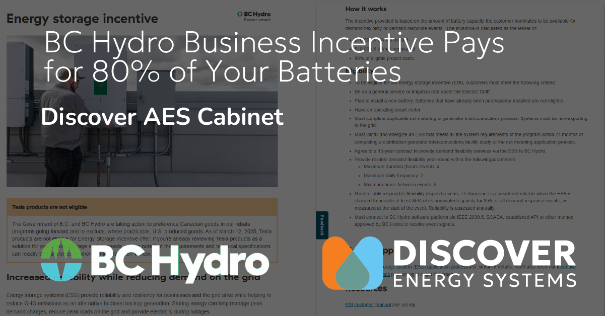
BC Hydro's ESI program encourages businesses to install a BESS. While the BESS benefits BC Hydro by assisting in managing energy usage when the grid experiences high demand, companies also benefit, as this incentive covers up to 80% of the cost of the BESS.
In addition to the BC Hydro incentive, the remaining cost of the BESS can be partly covered by the Canadian federal government’s clean technology investment tax credit. This credit is offered to businesses that invest in new, clean technology in Canada. To make it even better, companies can write off the net capital cost of the BESS in the first year (accelerated CCA) instead of charging the capital expense over two or more years.
That means businesses can reap the rewards of their own energy supply right away, and have it primarily paid for by BC Hydro and the federal government.
The following discusses the Energy Storage Incentive in more detail.
Energy Storage Incentive (ESI)
This is a BC Hydro rebate for commercial customers installing behind-the-meter battery systems. It is tied to a 10-year commitment to supply on-demand power through Distributed Energy Resource Management Systems (DERMS).
That means BC Hydro will pay 80%* of the cost of the BESS as long as it abides by the agreement's terms and delivers the expected energy.
* The ESI is calculated as the lesser of three different calculations, but 80% is the typical outcome.
Terms of Agreement
Eligibility
- The business must be a BC Hydro customer on an eligible business rate (e.g. small/medium/large general service)
- New battery installations only, with smart meter
- The design must be approved by BC Hydro before installation
BESS Performance Commitment
- Must respond to up to 2 events per day, each ≤ 4 hours, with ≥ 85% capacity available at event start
- Annual reliability ≥ 85% to avoid 10% annual claw‑back
Early termination of the 10 year agreement will trigger proportional repayment
Too Good to be True?
Like you, many businesses are wary of deals that appear too good to be true. And BC Hydro paying for 80% of an external company's BESS seems to fall into that category. Businesses are NOT clamoring all over each other to install their own BESS.
Why is that?
The answer is two-fold:
- Investment. Despite BC Hydro covering 80% of the cost of the BESS, the investment is significant.
For example, the cost of equipment and installation of a commercial BESS, including the inverter and peripheral equipment, could total between $500,000 and $2,000,000 CA, or more.
Although BC Hydro’s incentive would cover 80% of this cost, the business would still be responsible for the remaining 20%, which could range from $100,000 to $400,000 CA. - Claw-back. If the BESS does not perform as per the terms of the agreement, BC Hydro can seek reimbursement of funds from the business.
If the system is not configured correctly, businesses may have to return 10% of the incentive each year the BESS does not perform correctly.
Partner With Discover to Maximize Your Investment
By working with Discover Energy Systems, businesses can maximize their investment dollars.
Discover’s commercial and industrial batteries are competitively priced. Among available C&I batteries, Discover Energy Systems delivers some of the lowest cost per kilowatt hour.

One of Discover Energy’s flagship products, the AES 210HV Cabinet (209 kWh) with an inverter, peripheral equipment and installation, could cost between $135,000 and $150,000 CAD ($100,000 ~ $110,000 USD), which is less than most other C&I battery products available today.
Buy Local, Buy Canadian
Discover’s head office is located in Richmond, BC. Its roots are in the battery business for 75+ years in Canada. You can expect to receive excellent support for your local BC project.
Comply with BC Hydro's Performance Requirement
Discover has the tools and equipment that enable you to closely monitor and fine-tune battery performance, which is especially important in the early life of the system. To confirm the system is performing per the terms of the agreement, the system integrator can use Discover’s LYNK CLOUD to monitor the system and push event notifications to view and react to potential issues. Access to battery logs enables system integrators to identify problems and thereby modify the BESS configuration to maximize uptime, ensure energy availability, and comply with the terms of BC Hydro’s incentive program.
Summary
Discover Energy Systems' AES 210HV, well-suited for small to medium-sized battery projects, is a C&I battery that can take advantage of BC Hydro’s Energy Storage Incentive program. The cost of this BESS is less than that of most competing products. When combined with Discover’s monitoring tools, you can ensure the BESS meets BC Hydro's requirements, reducing a business's risk. After the 10-year commitment to BC Hydro’s DERMS program, the company will have complete control over the Battery Energy Storage System.
Contact Discover Energy Systems to see if installing the AES 210HV Cabinet is right for you.
Example to Illustrate Details About the ESI
AES 210HV (209 kWh) BESS with Sol-Ark 60K, 50% of battery capacity nominated for BC Hydro use, the other 50% for business use.
Example cost of system, including peripheral equipment and installation $150,000 CAD.
- Calculation of incentive from BC Hydro (choose the lesser of three)
- $10,000 × (kW nominated) → $10,000 x (60 kW x 50%) = $300,000
- $10,000 × (kWh nominated ÷ 4 hours) → $10,000 x (209 kWh x 50% ÷ 4) = $261,200
- 80% of eligible project costs (excluding ineligible items like insurance/building upgrades) → $150,000 estimated cost x 80% = $120,000
In this example, BC Hydro offers an incentive of $120,000, while the company's cost is $30,000.
- BESS Technical Criteria
Discover’s AES 210HV with Sol-Ark 60K inverter addresses all technical criteria.- ≥ 80% round-trip efficiency
- 10-year warranty
- UL/CSA certifications (UL 9540, UL 1973, UL 1741-SA, CSA standards)
- DERMS connection via IEEE 2030.5, SCADA, or approved API
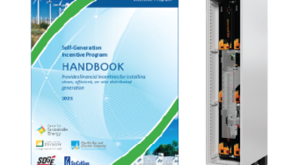
The Self-Generation Incentive Program (SGIP) has been available since 2001. It offers significant rebates for solar and battery storage systems. If you haven’t been paying attention, you’ve been missing out on money that’s been there for the taking.
According to the SGIP website, the Self-Generation Incentive Program (SGIP) may cover up to 100 percent of the cost of your solar and energy storage system, depending on your income and location.
This article is a simplified guide on how to get a rebate check after installing a solar energy and storage system.
|
Step |
Action |
|---|---|
|
Confirm residential/commercial customer and site eligibility |
|
|
Choose an SGIP-listed system (e.g., AES RACKMOUNT in Slimline Enclosure + Sol-Ark 15K) |
|
|
Submit SGIP reservation before purchase/install |
|
|
Install the system with a licensed installer |
|
|
Send the required completion and inspection documentation |
|
|
Receive a rebate per the utility guidelines |
|
|
Operate the system, meet discharge minimums as per SGIP guidelines, and maintain the equipment |
California’s Self‑Generation Incentive Program (SGIP) supports residential, commercial, nonprofit, and public agency installations of behind‑the‑meter battery storage systems. Residential customers of PG&E, SCE, or SDG&E are eligible, as are small businesses. Your system must be newly installed and meet SGIP technical guidelines.
2. Select SGIP‑Approved Equipment
SGIP provides rebates only if your system is on the official SGIP Verified Equipment List. Discover Energy Systems batteries on that list include:
- AES RACKMOUNT battery module (48 V, 5.12 kWh), listed for use with Sol‑Ark hybrid inverters.
- When configured in a Slimline enclosure (e.g. 4 modules for a 20 kWh system), paired with the Sol‑Ark 15K inverter, this qualifies as SGIP‑approved equipment.
These meet UL standards, warranty standards, and durability expectations required by SGIP.
3. Reserve Funds Before You Buy
Before purchasing or installing equipment, submit an online reservation application via the SGIP portal. This reserves your rebate budget and ensures you know your expected incentive tier before committing. Installation or purchases that occur before setting up a reservation can lead to disqualification.
4. Install the Approved System
Once your reservation is accepted, contact an approved installer so you can proceed with purchase and installation:
- Discover Energy’s Slimline enclosure populated with AES RACKMOUNT battery modules
- Sol‑Ark 15K hybrid inverter configured to integrate with these batteries
The licensed solar or electrical contractor will pull permits, enable safety inspections, and finalize the commissioning of the system.
5. Submit Post‑Install Documentation
After installation and inspection, submit documentation to SGIP:
- SGIP reservation details
- Copy of purchase/invoice
- Interconnection and other inspection certificates
- Solar and battery system capacity and inverter model
- Final proof of installation completion
SGIP administrators will verify compliance before issuing rebate funds.
Depending on your utility territory, rebates may be issued as:
- A one-time check
- A credit on your utility bill
For popular equipment bundles (e.g., Slimline with AES RACKMOUNT + Sol‑Ark 15K), rebate levels may cover 80% or more of the system cost, depending on your energy tier and income level. In some equity-eligible programs, households or underserved communities may qualify for full coverage.
7. Maintain and Operate Your System
SGIP requires that installed systems perform at least 52 full discharge cycles per year and remain stable. Maintain the system per manufacturer guidelines and maintain warranty and SGIP compliance documentation. Avoid relocating or substantially modifying the system without notifying SGIP administrators, as this may affect eligibility.
To get started, contact a qualified installer and ask to use AES RACKMOUNT battery modules from Discover Energy Systems.

SGIP Rebate in California
Here’s a simple rebate calculation for a residential energy storage system using Discover Energy’s AES RACKMOUNT modules in a Slimline enclosure, paired with the Sol‑Ark 15K inverter—to demonstrate the potential SGIP rebate you can earn.
Typical System Configuration
Let’s assume a 20 kWh battery energy storage system installed with the Sol‑Ark 15K inverter:
- AES RACKMOUNT modules (e.g., 4 × 5.12 kWh modules = approximately 20 kWh)
- Installed by a licensed installer (with permits and inspection)
- Pair the batteries with solar panels to potentially qualify for further SGIP rebates in addition to federal rebates from the Solar Tax Credit (ITC). Check the SGIP portal for information on what incentives are available in your location.
Incentive Rebate Rates under SGIP (2025)
- Standard residential rate: $0.85 per Wh of storage, depending on the incentive step and equity status results in $850 per kWh.
Solar is not eligible for a rebate at this level. - Equity-resiliency (low-income or high-fire-threat areas): $1.10 per Wh of storage, which converts to $1,100/kWh for the batteries, and $3.10 for each watt of solar.
Rebate Calculation
The following calculation assumes a 7 kW solar array.
- Standard Tier: $0.85 per watt, or $850/kWh
Rebate = 20,000 Wh × $0.85 = $17,000
TOTAL Rebate = $17,000 - Equity-Tier or High-Fire Zone: $1.10 per watt, or $1,100/kWh
Rebate = 20,000 Wh × $1.10 = $22,000 PLUS 7000 watts x $3.10 = $21,700
TOTAL Rebate = $43,700
Net System Cost
Batteries + Inverter
Assuming the net cost for equipment (batteries and inverter) is $25,000:
- Standard Tier with $17,000 rebate → the net cost is $8,000
- Equity Tier or High-Fire Zone with $22,000 rebate → the net cost is $3,000
Solar + Batteries + Inverter
Assuming the cost of equipment (solar, batteries, and inverter) is $40,000:
- Standard Tier with $17,000 rebate → the net cost is $23,000
- Equity Tier or High-Fire Zone with $43,700 rebate → the net cost is $0 (FREE!)
Depending on your location, customer status, and the system you install, up to 100% of the system cost could be covered by the SGIP rebate. Any remaining costs for the system could net a further 30% federal rebate under the Solar Tax Credit (ITC).
----------------------------------------------------------------------------
Ready to Get Started?
Contact an approved installer and ask to use the Discover Energy Systems batteries.
Why Discover?
- SGIP-listed equipment: Our AES RACKMOUNT modules are expressly listed on the SGIP Verified Equipment List, along with compatible Sol‑Ark 15K inverters.
- Field‑tested configuration: Real-world installations regularly partner the Slimline battery enclosure with Sol‑Ark 15K units, meeting SGIP performance specs.

